Quick start: your first board in five steps
Open the designer. A small perfboard is ready to use, and your work is saved in the browser as you go, so there's nothing to set up first.
-
Pick the board
In Board, choose Perfboard or Stripboard, then a preset size or the number of holes across (W) and down (H), and click Resize.
-
Place the parts
Search the Components list (press /), click a part, then click the board where it goes. A resistor or LED takes two clicks: one hole for each lead.
-
Wire it up
Press W for the wire tool, click the pin where a wire starts, then each hole it runs to. Press Esc to finish.
-
Check the nets
The Nets panel on the right lists which pins are connected. Click a net to light it up on the board, and look out for pins left unconnected.
-
Share or save it
Click Share to copy a link to the board, or use the File menu to save a project file or download a PNG or SVG picture.
The editor at a glance
The editor has four areas:
- Header: the File menu (new, open, import, save, share, download), the View menu (fullscreen, 3D view, show or hide the side panels), the name of the open project (click it to see all your projects), and the Share and 3D View buttons.
- Left sidebar: Tools (Select, Eraser, Note, and Cut on a stripboard), Undo and Redo, Board type and size, the Wire tool with its colors and thicknesses, and the Components library.
- Board: the hole grid you design on, with zoom, Fit, Labels and Fullscreen above it. The badge at the top left tells you what the next click will do, and the bar underneath shows the note or value of whatever you point at.
- Right sidebar: the live Nets panel and the list of keyboard shortcuts.
Tip: the badge above the board always says what the current tool expects, such as "Click start pad" or "Click end pad". If you're unsure what a click will do, read it, and press Esc to back out.
Set up the board: perfboard or stripboard, any size
A perfboard has a separate copper pad around every hole, so nothing is connected until you wire it. A stripboard (often sold as Veroboard) has copper strips running along every row or column, so every hole on a strip is already connected. Pick the type in the Board panel; you can switch at any time and your parts and wires stay where they are.
Board size
Holes are 2.54 mm (0.1 inch) apart, the standard pitch for through-hole parts. Type the number of holes across (W) and down (H) to match the board on your bench and click Resize, or click a preset such as 5x7 or 7x9 (in centimetres, the sizes boards are sold in).
Resizing keeps every part and wire that still fits. If making the board smaller would cut something off, the editor asks first, and a resize can't be undone.
Place components
The Components list holds the whole part library in categories: passives (resistors, potentiometers, capacitors, crystals, fuses, inductors), semiconductors (LEDs, diodes, transistors, MOSFETs), ICs (timers, logic, microcontrollers, op amps, regulators, drivers, optocouplers), modules and dev boards (Arduino Nano, ESP32, Raspberry Pi Pico, Wemos D1 Mini), connectors, switches, displays, sensors, batteries, relays and buzzers.
Press / to jump to the search box and type a name, a value or a part number, such as "555", "header" or "electrolytic". Parts you've placed recently are listed under Recently used… at the top, so you can grab them again quickly.
Click a part to pick it up. How you put it on the board depends on the part:
Two-lead parts
Resistors, capacitors, LEDs, diodes and inductors bend to fit. Click the hole for the first lead, then the hole for the second; the body is drawn between them.
Fixed-footprint parts
Transistors, pots, switches, connectors and displays have fixed pins. Press R to turn the part, then click the hole to drop it. Header pins and female headers take two clicks: two opposite corners of the block.
ICs and dev boards
DIP chips and dual-row modules are placed with one click, with pin 1 at the notch. Press R before placing, or later with the chip selected, to rotate it.
A part stays picked up so you can place several in a row. Press Esc or click Select to put it down. Every part gets a reference designator automatically: R1, R2 for resistors, C1 for capacitors, D1 for diodes and LEDs, U1 for chips, J1 for connectors, and so on.
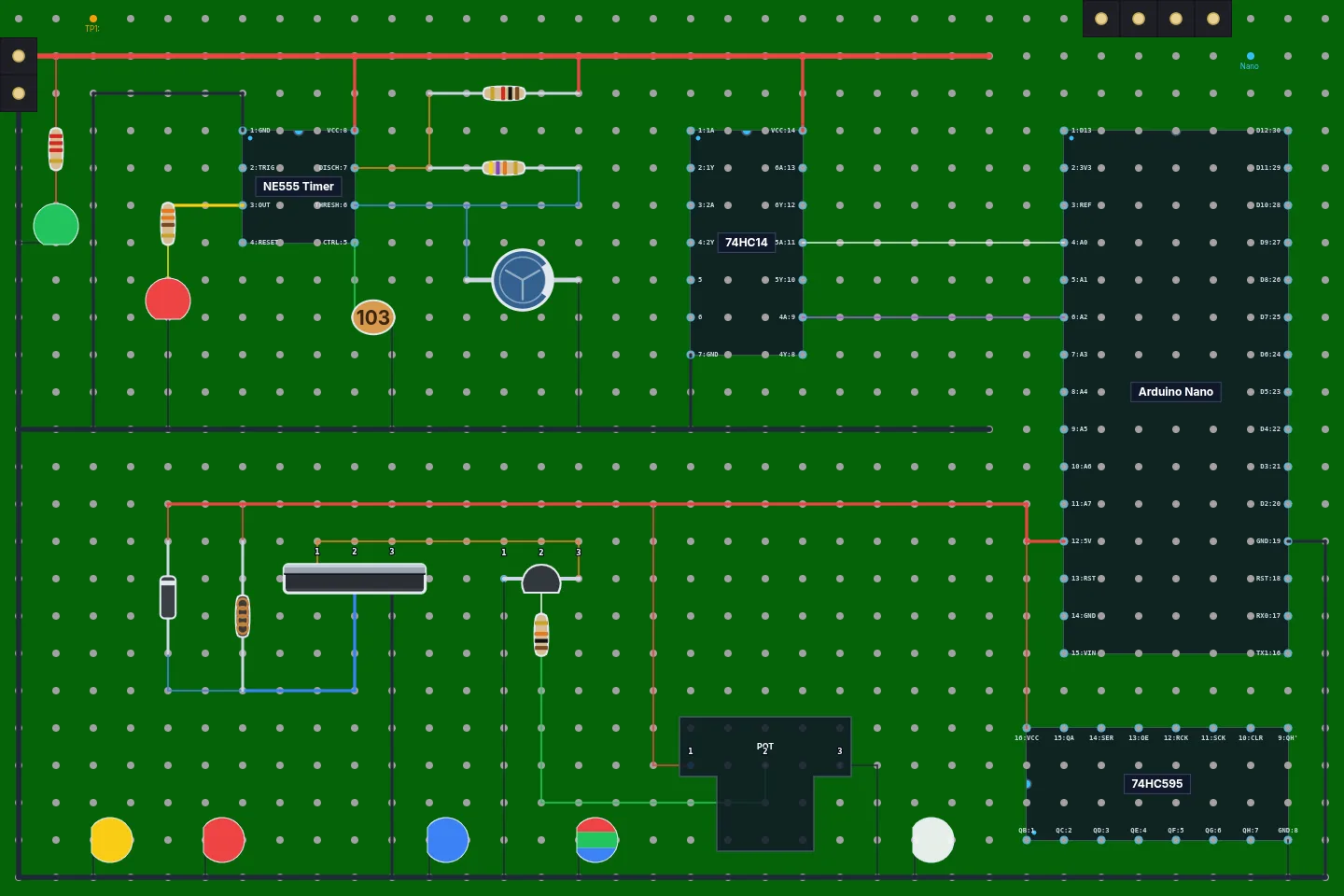
Values, colors and labels
Right-click a part for its menu. Set Value gives a resistor its
resistance, a capacitor its capacitance, and so on. Values understand the usual prefixes:
4k7, 4.7k, 100n, 10u. The drawing
follows the value: a resistor gets the right color bands, and a ceramic capacitor the
three-digit code printed on it (such as 104 for 100 nF).
For an LED, Change Color picks red, green, blue, yellow or RGB. Click Labels above the board to show every part's name and value right on the board (for example "R1 10k"), handy when you print the layout to solder from.
Custom ICs and modules
If a chip or breakout board isn't in the library, make it. Click Custom… at the top of the Components list to open the editor, then set:
- Name, such as "ESP8266-01" or "LM2596 module".
- Type: an IC, listed under ICs › Custom, or a module, listed under Modules › Custom.
- Body width in holes, including both pin rows, and the number of pins per side.
- A label for every pin, numbered from pin 1 at the notch, like a datasheet.
Custom parts are kept in your browser and travel with every project and share link that uses them, so a board opens with its chips intact on any computer.
Route wires
Click Wire Tool or press W. Click the hole where the wire starts, then click each hole it should run to: every click ends one straight segment and starts the next, so you can route around parts with corners. Click the same hole twice or press Esc to end the run.
- Pick a color before you draw (red for power and black for ground keeps a board readable), or add your own with the + button.
- Choose Thin, Normal or Thick wire.
- Straight runs of the same color that meet end to end are merged into one wire.
- To recolor a wire, select it and click a color.
How wires connect
Wires are insulated jumpers, like the ones you solder on the back of a board. A wire only connects the holes at its ends. Where it runs across another wire, or over a hole that holds a pin, it passes over without touching: the editor draws a dark edge along it there. Where three or more things meet in one hole, a solder dot marks the joint. To connect two wires, end them in the same hole.
Select, move and delete
- Select (the default tool): click a part, wire or hole to select it. Drag a part to move it to new holes.
- Right-click anything for its menu: Rotate Component, Change Color, Add/Edit Note, Set Value and Delete Item.
- Delete removes the selected part or wire.
- Eraser: click a part or wire to remove it, or a hole to clear its color and note.
- Note: click a hole to write a note on it, such as "to 9V battery" or "solder last". Notes show in the bar below the board when you point at the hole. With a hole selected, D adds a note and Shift+D removes it.
- Undo and Redo with Ctrl+Z and Ctrl+Y, or the buttons under the tools.
Stripboard (Veroboard) layouts and strip cuts
Switch the board to Stripboard and choose Horizontal or Vertical strips. Every hole along a strip is connected, so parts on the same strip are joined without a wire, and the Nets panel counts the strips as connections.
To separate two parts on one strip, cut it: pick the Cut tool (it appears in Tools on a stripboard) and click the hole where the strip should break. A cut hole connects to nothing. Click it again to mend the strip. The classic case is a DIP chip across horizontal strips: cut the strips under the chip's body so pin 1 isn't joined to pin 8, and so on.
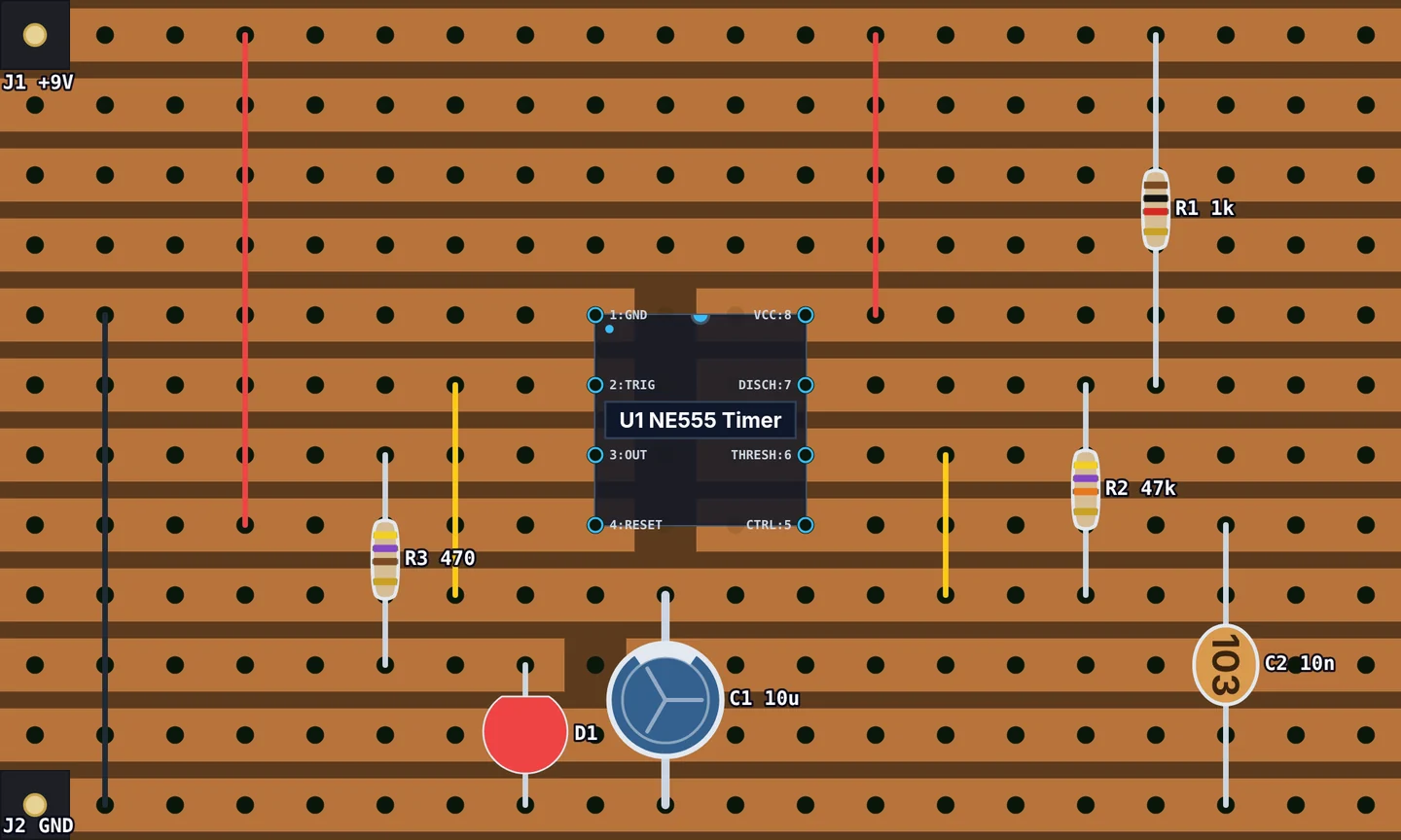
Cuts are saved with the project and drawn on the copper side of the 3D view. If you switch back to perfboard, the cuts are kept, hidden, and come back when you switch to stripboard again.
Check connections with the Nets panel
A net is a set of pins that are electrically connected. The Nets panel on the right works them out live from your wires, shared holes and, on a stripboard, the strips and cuts. Each net is named from its pins where it can be, for example GND, VCC or OUT, and lists its pins as "U1.8 VCC", "R1.1" or "D1.K" (the LED's cathode).
- Click a net to highlight its holes and wires on the board; click it again to turn the highlight off.
- Not connected lists pins wired to nothing, the most common slip on a real board.
- Connecting no pins lists wires that don't reach any part.
Before you solder: go through your schematic net by net and check each one in the panel. A net named like "GND/VCC" means two supply rails are shorted, often by an uncut strip.
Perfboard Designer checks how the board is wired, not how the circuit behaves: it doesn't simulate your circuit.
Preview the board in 3D
Click 3D View to see your layout as a 3D model of the finished board: resistors with their color bands, chips with labeled pins, LEDs, capacitors, connectors and every jumper wire, arched over the wires it crosses.
- Drag to orbit and scroll to zoom.
- Angled, Top and Bottom jump to a preset view; Bottom shows the copper side with its strips, cuts and solder joints.
- Screenshot saves a picture of the render.
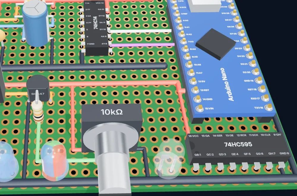
The 3D view needs WebGL. If it doesn't open, turn on hardware acceleration in your browser's settings or try another browser.
Save, share and export
Projects in your browser
Every board is a project, saved automatically in your browser as you edit. Click the project name in the header, or File › Open Project…, to see them all with thumbnails, and open, rename, duplicate or delete them. File › New Project… starts a fresh board.
Keep a backup: browser storage is cleared if you clear your site data. Use File › Save Project to File… to download a project file, and Import Project from File… to open it again on any computer.
Share links
Share (or File › Share Link…) makes a link that carries the whole board inside it. Whoever opens it gets their own copy as a new project; your board isn't changed, and nothing is uploaded. The link is a snapshot: after more edits, share a new one.
For a link short enough for a forum post or a chat, click Make Short
Link and give it a name, such as led-blinker. That stores a copy
of the board on Perfboard Designer's server under that name. Anyone with the link can open
it, the stored copy never changes, and it's deleted after a year unopened.
Images for printing and documentation
File › Download Image (or P) saves the board as a PNG, and Download SVG as a sharp vector image you can scale or print at any size. Turn on Labels first to include part names and values.
Design boards with an AI assistant
Perfboard Designer has a free MCP server, so Claude, ChatGPT, Cursor and other AI assistants can lay out boards for you. Describe the circuit, such as "a 555 LED blinker on a small perfboard", and the assistant picks the parts, places them, routes the wires, checks every connection and gives you a link that opens the board here, ready to change. It can also read a board you share with it and edit it.
Keyboard shortcuts
| Keys | What it does |
|---|---|
| / | Search components |
| W | Turn the wire tool on or off |
| R | Rotate the part you're placing, or the selected part |
| Esc | End a wire run, put down the part you're placing, or clear the selection |
| Delete | Delete the selected part or wire |
| C | Change the color of the selected hole |
| D | Add a note to the selected hole |
| Shift+D | Remove the selected hole's note |
| M | Move the selected hole's color and note to the hole under the pointer |
| Ctrl+Z | Undo |
| Ctrl+Y | Redo |
| P | Download the board as a PNG image |
| Space + drag | Pan the board with any tool |
The same list is always in the editor's right sidebar.
Tips for a clean perfboard layout
- Start with the big parts. Place chips, dev boards and connectors first, leaving room around them, then fit the small parts in between.
- Plan the power rails. Run power and ground along the board's edges or along two strips, so every part can reach them with a short wire.
- Put connectors at the edge, where cables can reach them without crossing the board.
- Leave a spare row or column around the edge for mounting holes and last-minute changes.
- Use a color code for wires: red for power, black for ground, and one color per signal you'll want to trace later.
- Keep wires short and straight, and avoid running wires under parts, where you can't reach them with the iron.
- On stripboard, cut under every DIP chip and check the Nets panel for shorts before you solder.
- Mind polarity: the Nets panel names an LED's or diode's leads A and K and a capacitor's + and −, so check them against your schematic.
- Print it. Download the image with labels on and keep it next to the board while you solder.
Frequently asked questions
How do I cut a strip on a stripboard?
Switch the board to Stripboard, pick the Cut tool in the Tools panel and click the hole where the strip should break. Click a cut hole again to mend it.
How do I rotate a component?
Press R. It turns the part you are about to place, or the selected part on the board. You can also right-click a part and choose Rotate Component.
Why are two wires that cross not connected?
Wires are insulated jumpers: a wire only connects the holes at its two ends. Where it runs over another wire or a hole it goes over it without joining. To connect, end the wires in the same hole.
Where are my projects saved?
In your own browser, automatically as you edit. Use File › Save Project to File to keep a copy on disk, or Share Link to send the board to someone.
Can I share a board without an account?
Yes. File › Share Link makes a link that carries the whole board. Whoever opens it gets their own copy as a new project. No account is needed.